Matrix math for 3d graphics
This document focuses on 3D affine transformation matrices, which take the form of a 4x4 matrix:
is the element at the given row and column index (0-based).
A standard affine matrix, represented in column-major form, it looks like this:
Where , and are their respective axes, such as , and in the case of an identity matrix, and represents the translation.
Column-Major and Row-Major
Column-major and row-major is the most important property, because it determines both how the matrix is read and how operations on it are performed.
Column-Major
Column major matrices use column-vectors, and the matrix is composed of three column-vector bases. A column-vector takes the form:
This is a four-component vector because affine transformations use homogeneous coordinates, which require a forth component (typically set to 1).
The columns of the matrix represent the bases (or axes) of the coordinate system, and the translation values are stored in the , , elements.
Vectors are right- or post-multiplied to matrices:
Matrix multiplication call order is the reverse of the order the transforms are applied, reading from right-to-left: "take , transform by , transform by , transform by " is written as:
Row-Major
The primary properties of row-major matrices are the opposite of column-major matrices.
They use row-vectors:
The rows of the matrix represent the bases (or axes), and the translation values are stored in , and .
Vectors are left- or pre-multiplied to matrices:
Matrix multiplication call order and the order the transforms are applied is the same, reading from left-to-right: "take , transform by , transform by , transform by " is written as:
C-based languages access arrays in row-major order:
const float M[4][4] = {
    {  0,  1,  2,  3 },
    {  4,  5,  6,  7 },
    {  8,  9, 10, 11 },
    { 12, 13, 14, 15 },
};

// Accessed as M[row][column].
EXPECT_EQ(0, M[0][0]);
EXPECT_EQ(1, M[0][1]);
EXPECT_EQ(4, M[1][0]);

// In-memory, the array is laid out like so:
// { 0, 1, 2, 3, 4, 5, 6, 7, ... }

// So to calculate the position in memory, C-based languages perform:
const float* M_ptr = M;
float getValue(size_t row, size_t column) {
    return M_ptr[row * 4 + column];
}

EXPECT_EQ(M[0][0], getValue(0, 0));
EXPECT_EQ(M[0][1], getValue(0, 1));
EXPECT_EQ(M[1][0], getValue(1, 0));
Left Handed vs. Right Handed
For left-handed vs. right-handed, a picture is worth a thousand words. For a given coordinate system, orient the thumb along the positive X-axis, the index finger along the positive Y-axis, and the middle finger along the positive Z-axis. If it's possible to do this with the right hand, the coordinate system is right-handed, and vise-versa.
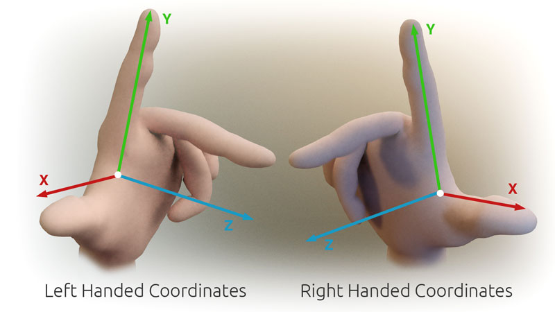
Image credit: Primalshell
Left-handed or right-handed coordinate systems determine how the axes relate to each other, specifically for the Z-axis compared to X and Y. There are multiple orientations that are valid for each rule, and sometimes it's difficult to orient the hand to align, but the rule still holds true for each orientation.
To determine if a given coordinate system is left-handed or right-handed, the cross product can be used.
For right-handed coordinate systems, the cross product of and bases yield . The cross product is natually right-handed:
For left-handed coordinate systems, the z-axis is negated:
Handedness and Rotations
Handedness also changes rotations around an axis. For an observer looking at the axis that is rotating, as if you are looking at your hand along the axis that is rotating (For Z-axis rotations, looking towards your middle finger), positive rotations are:
| Right-Handed | Left-Handed |
|---|---|
| Counter-clockwise | Clockwise |
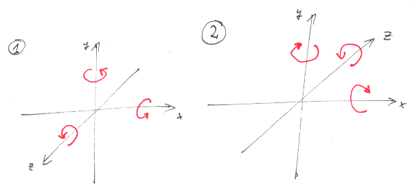
Image credit: mufnull
This means that for the standard 2D coordinate system is actually right-handed, with a virtual Z-axis extended out from the paper.
Other Differences
Y-Up vs. Z-Up
- Why the difference? It depends on the 3D library's use case and how it perceives the world.
- Imagine each method starts in 2D, and the Z-axis is grafted onto it.
- With +Y up, the 2D graph is placed on a monitor, with +X to the right, and depth is added by going into the monitor.
- With +Z up, the XY coordinates are placed horizontally, like a piece of graph paper on the table, and Z changes the altitude.
Who Uses What?
Here is a table which lists the default properties of matrices and coordinate systems for various libraries. Note that for handedness it may be possible to use either, but the default is listed below.
| OpenGL | DirectX | Unity | Unreal | |
|---|---|---|---|---|
| Handedness | Right-handed1 | Left-handed | Left-handed | Left-handed |
| Up Direction | +Y up | +Y up | +Y up | +Z up |
| Layout | Column-major2 | Row-major | Column-major | Row-major |
OpenGL
As noted above, OpenGL notation is typically column-major, but the in-memory layout is row-major.
For a row-major storage, matrix access in the form of accesses memory laid out in this form:
Or put in the terms of an affine transform:
DirectX
DirectX also uses a row-major memory layout, but because it also uses row-major conventions, it maps logically reading left-to-right:
Citations
- World Coordinate Systems in 3ds Max, Unity and Unreal Engine
- Row Major vs Column Major Vector
- Understanding OpenGL's Matrices
- OpenGL Transformations FAQ
- Stack Overflow Answer: Is OpenGL coordinate system left-handed or right-handed?
- Stack Overflow Answer: Right-Handed Euler Angles XYZ to Left-Handed Euler Angles XYZ
- Stack Overflow Answer: Confusion between C++ and OpenGL matrix order (row-major vs column-major)
- OpenGL notation is typically column-major, as seen in the OpenGL specification and the OpenGL reference manual, but the in-memory layout is row-major. See question 9.005 in the FAQ on this page.↩
- OpenGL is right-handed in object-space and world-space, but left-handed in screen-space. See this stack overflow post.↩